***************************************************************************************************************************************************
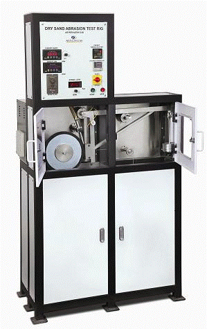
DRY SAND ABRASION TEST RIG AS PER ASTM G 65

The DRY SAND ABRASION TEST RIG has been designed as per ASTM G 65 specifications. This test uses a rubber-rimmed wheel as the bed for silica abrasive that is fed from a hopper by a nozzle between the sample and the wheel. The sample is pressed into the wheel by a dead weight loaded lever. The test is run for a set number of revolutions with automatic cutoff and the wear is measured by measuring the volume of material lost through mass loss and density measurements.
The flow of sand into the gap between the surfaces is controlled by the geometry of the nozzle that must be very carefully defined to obtain the required sand flow rate. The abrasive only passes through the wear interface once and is thrown away at the end of the test.
The uniform loading and uniform flow of abrasive into the gap between wheel and the specimen under controlled conditions give consistent results. The properties of the rubber lining of the wheel also have a major effect on the results and need to be carefully controlled.
Technical Specifications of Dry Sand Abrasion Test Rig as per ASTM G 65
- Abrasive - AFS 50 – 70 test sand (about 200 micron size)
- Wheel speed – 100 - 500 rpm continuously variable through AC frequency inverter with helical geared motor of 1.5 Kw (3 phase)
- Abrasive flow rate – 50 – 500 gms/min through precision conveyor mechanism
- Test load - 45 to 130 N
- Wheel diameter – 228 mm
- Chlorobutyl rubber hardness – A 58 to 62 on a Shore Durometer.
- Revolutions controller – Microprocessor based digital preset counter 1rev. to 9999 revs.
- RPM Indicator (for measuring the rubber wheel speed)
- Power input – 440V, 3Phase, 15 Amps
- Specially designed stainless steel nozzle for accurate abrasive flow.
- Stainless steel loading arm with a lifting cam and easily changeable dead weights.
- Stainless steel hoppers for abrasive feed and dust collection.
- Stainless steel dust collection container.
- Sheet metal fabricated and powder coated storage space for specimen, wheels and dead weights.
- The frame of the machine is made of tubular section and powder coated.
- The test area is enclosed in a dust proof cubicle with a glass door and suitable illumination for viewing the specimen during the test.
- The entire test rig is designed so as to protect the user from the dust emerging from the machine during the test duration.
- The entire test rig is mounted on anti vibration mounts so as to ensure the accuracy of the test and prevent noise.
- Chlorobutyl rubber rimmed wheels – one mounted on machine and one given as a spare.
- 3 Types Reference materials supplied along with the machine (each 05nos)
- AISI D-2 Tool steel (IS 165 CR MO12 HRC 58-60 HRC) Procedure – A
- AISI H-13 (Die steel) HRC 47- 48 Procedure – B
(c) AISI 4340 steel HRC 3133 Procedure – B or E
Optional
- Temperature measurement under the test surface with K type thermocouple and digital temperature
- Chloro-butyl rubber rimmed wheels.
